Traversing:
Traversing defined as a surveying that involves a series of connected lines is understood as ‘Traversing,’ the edges of the traverse are referred to as ‘traverse legs’
In traversing, the lengths of the lines arc measured by chain and therefore the directions are fixed by compass or theodolite or by forming angles with chain and tape.
Types Of Traverse
Closed Traverse
When a series of a connected lines forms a loop , i.e, when the finishing point coincides with the start line of a survey, it’s called a closed traverse. Here ABCDEA represents a closed traverse (Fig. 3.7).
Closed traverse is compatible to the survey of boundaries of ponds, forests, estates, etc.
Open Traverse
When a sequence of connected lines extends along a general direction and doesn’t return to the start line , it’s referred to as ‘open traverse’ or ‘unclosed traverse’. Here, ABCDE represents an open traverse (Fig. 3.8).
Here the open traverse is compatible for the survey of roads, rivers, coast lines, etc.
Methods Of Traversing
Traverse survey could also be conducted by the subsequent methods:
1. Chain traversing (by chain angle),
2. Compass traversing (by free needle),
3. Theodolite traversing (by fast needle) and
4. surveying instrument traversing (by plane table).
Chain Traversing
Chain traversing is especially conducted when it’s impossible to adopt triangulation.
During this method, the angles between adjacent sides are fixed by chain angles.
The whole survey is conducted by chain and tape only and no angular measurements are taken.
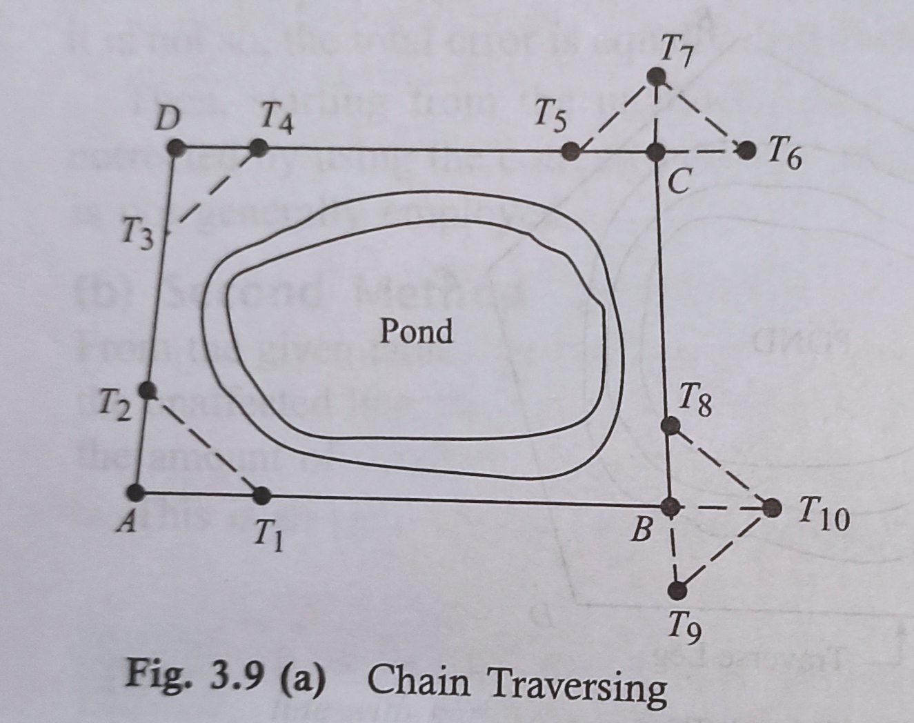
When it’s impossible to make triangles, as, for instance , in a pond, chain traversing is conducted, as shown in (Fig. 3.9).
The formation of chain angles is explained below.
First Method: Suppose a sequence angle is to be formed to discern the directions of sides AB and AD. Tie stations T₁and T₂ are fixed on lines AB and AD.
The distances AT₁, AT₂ and T₁T₂ are measured. Then the angle ⟨T₁AT₂ is claimed to be the chain angle. So, the chain angle is fixed by the tie line T₁T₂ Fig. 3.9(a).
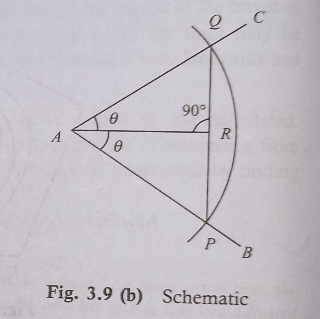
Second Method: Once in a while the chain angle is fixed by a chord. Guess the angle in the lines AB and AC is to be fixed.
Taking A because the centre and a radius adequate to one tape length (15 m), an arc intersecting the lines AB and AC at points P and Q, respectively, is drawn. The chord PQ is measured and bisected at R shown in Fig. 3.9(b).
Let ⟨PAR = θ
Then ⟨BAC = 2θ
Here, AP=AQ = 15 m
In triangle ∆PAR,
sinθ = PR/AP=2PR/2AP=PQ/30
θ = sin-¹PQ/30
The angle θ will be calculated from the above equation, and therefore the chain angle ⟨BAC may be determined accordingly.
Compass Traversing
In this method, the fore and back bearings of the traverse legs are measured by a prismatic compass and therefore the sides of the traverse by chain or tape. Then the observed bearinɡs are verified and necessary corrections for local attraction are applied. during this method, closing error may occur when the traverse is plotted. This error is adjusted graphically by using Bowditch ‘s rule.
Theodolite Traversing
In theodolite traversing, the horizontal angles into the traverse legs are measured by the theodolite.
And measured the lengths of the legs by the chain or by employing the stadia method. The magnetic bearing of the starting leg is measured by a theodolite.
Then the magnetic bearings of the opposite sides are calculated. The independent coordinates of all the traverse stations are then pointed out. This method is extremely accurate.
Plane Table Traversing
In this method, a plane table is ready at every traverse station within the clockwise or anticlockwise direction, and therefore the circuit is finally closed.
During traversing, the edges of the traverse are plotted consistent with any suitable scale. At the tip of the work, any closing error which can occur is adjusted graphically.
Check On Closed Traverse
1. Check on Angular Measurements
The total of the measured interior angles should be equal to (2N — 4) x 90° where N is that the number of sides of the traverse.
The sum of the measured exterior angles should be equal to (2N+ 4) x 90°.
And the algebraical sum of the deflection angles should be equal to 360°.
Right-hand deflection is taken into account positive and left-hand deflection, negative.
2. Check on Linear Measurement
Hence the lines can be measured once each on two different days (along opposite directions). Both measurements should tally.
And the linear measurements should even be taken by the stadia method. The measurements by the chaining and by the stadia method should tally.
Check On Open Traverse
In open traverse, the measurements can’t be checked directly. But some field measurements are often taken to ascertain the accuracy of the work. The methods are discussed below.
1. Taking Cut-off Lines of Check on Open Traversinɡ
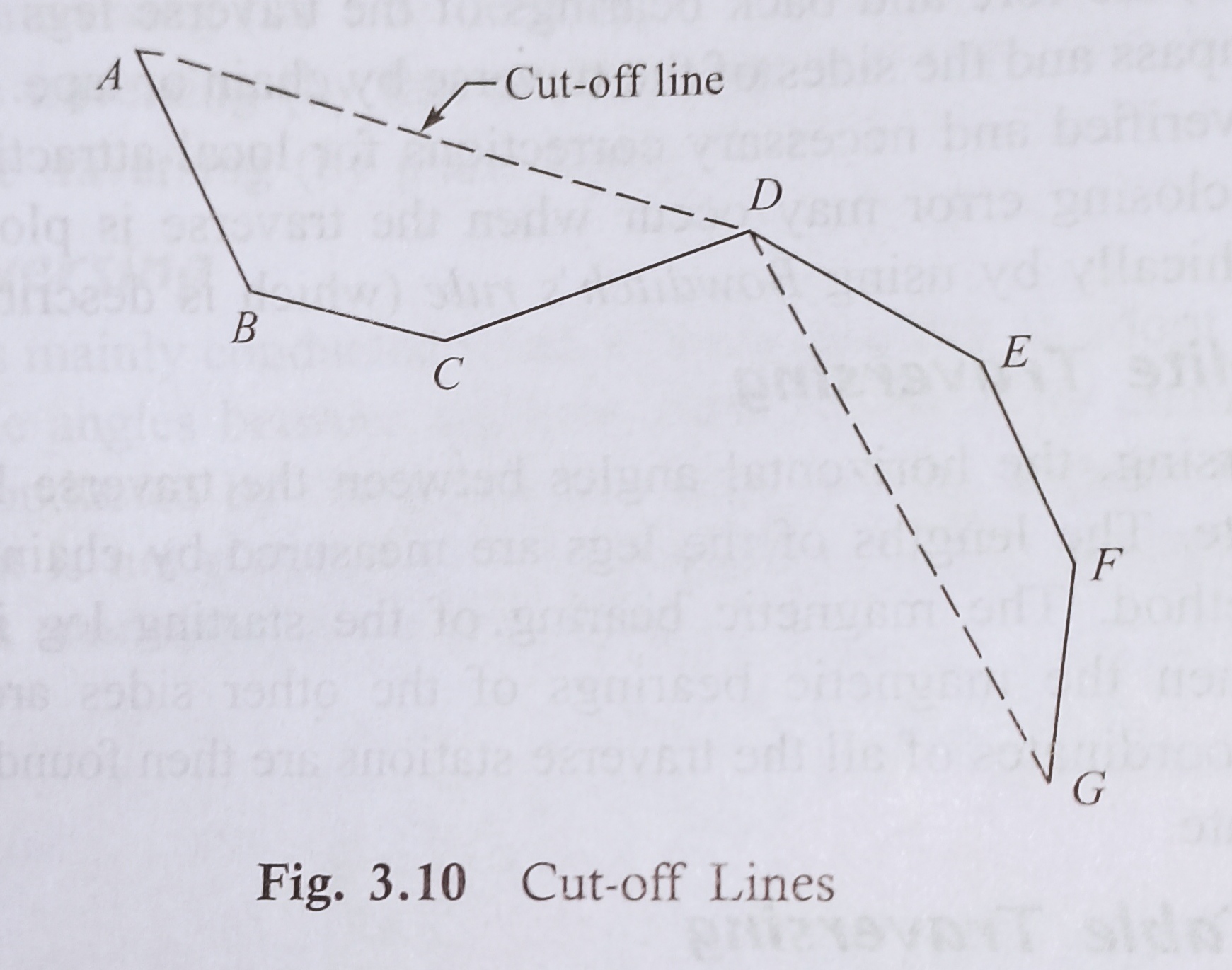
The cut-off lines are taken between some intermediate stations of the open traverse. Suppose ABCDEFG represents an open traverse.
Let AD and DG be the cut-Off lines. And the magnetic bearings and lengths of the cut-off lines are measured accurately.
Then plotting the traverse, the distances and bearings are noted from the map. These distances and bearings should tally with the particular records obtained from the field (Fig. 3.10).
2.Taking an Auxiliary Point of Check on open Traversinɡ
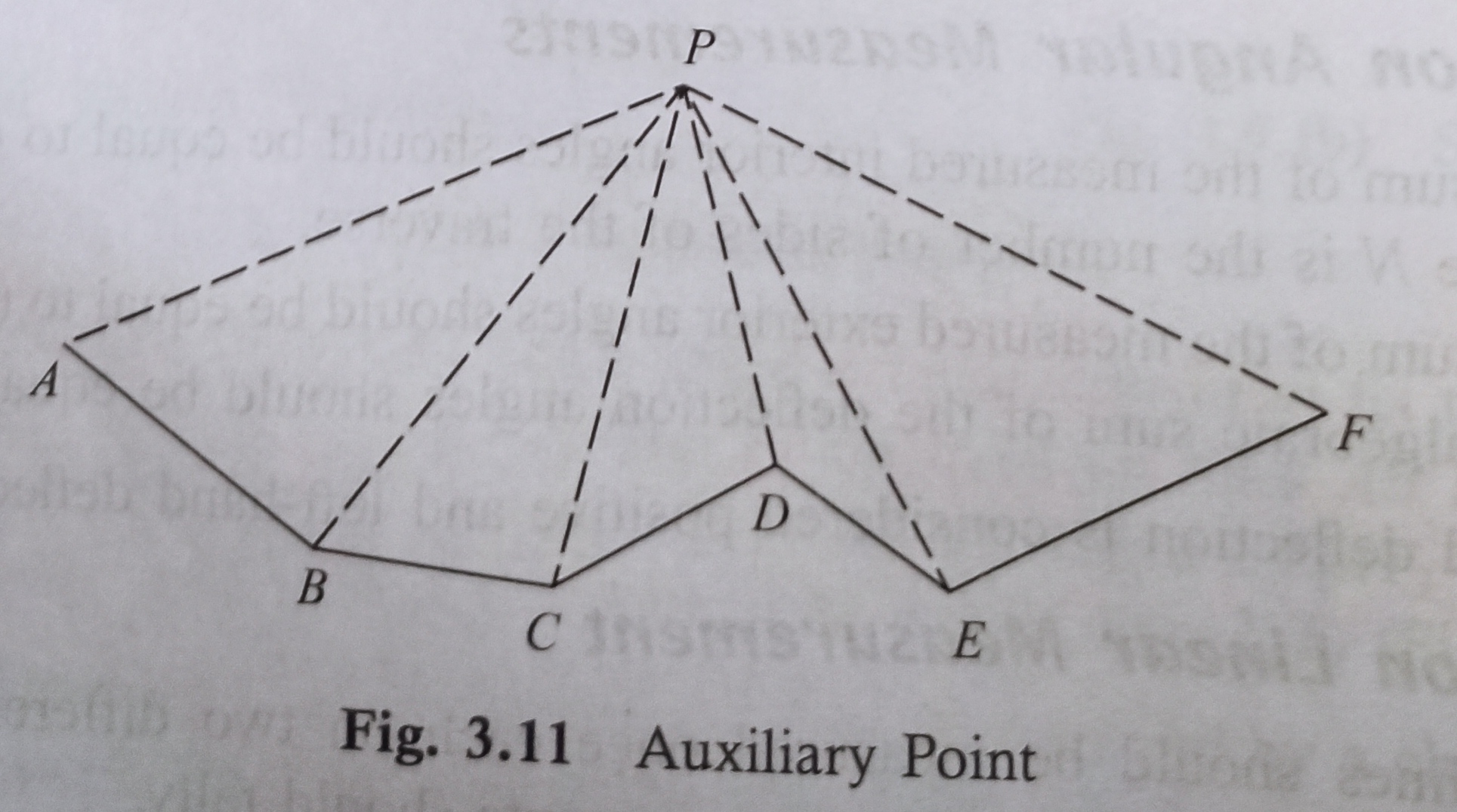
Suppose ABCDEF is an open traversinɡ. A adjustable point P is elected on 1 side of it. And then taken the magnetic bearings of this point from the traverse stations A, B, C, D, etc.
If the survey is administered accurately then is that the plotting, all the measured bearings of P when plotted should meet at the purpose P. The permanent point P is understood as the auxiliary point (Fig. 3.1 1).
Basics of Surveying & Levelling


